
Approaching a certain quality level of switching and routing, high availability evolves to be an obligation. In these terms, according to the different OSI service layers, there are many high availability protocols, securing the according network services. The Spanning Tree family as STP, RSTP, MSTP, PVST, protocols for link aggregation as LACP and layer three routing redundancy services like VRRP.
These protocols have the advantage, being vendor independent standards and presume to be interoperable. But either design gets complex, interoperability keeps its caveats or ressources are simply disabled and take over in failiure. Thats not exactly performance driving.
So vendors created stacks – which failed otherwise, or they started to create systems of higher complexity which proprietary created load sharing high availability clusters in the network. Eventually this development lead to the TRILL standards and implementation of CISCO Nexus fabricpath and more.
HPE – H3C with the comware based systems developed their TRILL – Transparent Interconnection of Lots of Links – approach called IRF, Intelligent Resilient Framework, which as far as I’m concerned does the job pretty well so far. Nevertheless the IRF needs to be planned accordingly, since there are topology guidelines, which need to be obeyed.
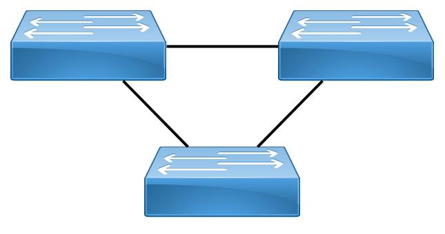
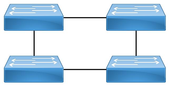
Basically up to four devices built an IRF ring. Each device may have configured two IRF ports, that form that ring.
Or create a ring as in the teaser image out of three switches. Given a real ring the topology is easy, on of the two IRF ports to each of the adjacent neighbors. The topology resulting for a pair of switches therefor is a little bit different. Intuitively you may think of creating two different links or not distinguishing the IRF port groups.
Very important caveat: this is not the case. Setting up a switch pair, results in a need to create one link between the two switches containing on one switch the IRF port group one and on the second the port group two. Any other combination – both switches configured on IRF port group one/two or a loop with two configured connections between only the two switches should not work. As far as I tested, it didn’t.

There are many other considerations, how to place an IRF fabric in a further setup with neighboring other IRFs or traditional connections, which may be discussed in another post. Important sidemark here is, that multichassis link aggregation groups and the distributed routing engine do provide lots of inherent redundancy for flat network topologies around an IRF.
Given now a two switch setup, this results in following configuration steps, taking two FF5700 with the IRF connections set on the FourtyGig interfaces. As one really strongly recommended preparation, first upgrade all switches to an identical firmware version. The configuration-process runs as follows:
To allow different IRF environments in one network and to ensure that only the switches form an IRF which are supposed to first define a unique IRF domain on the group of switches, configure on every switch.
irf domain 10
If you doublecheck with display irf you may see on all switches that they think they are number one and master:
MemberID Role Priority CPU-Mac Description

*+1 Master 32 00e0-fc0f-8c02 ---

-------------------------------------------------------------

* indicates the device is the master.

+ indicates the device through which the user logs in.
The bridge MAC of the IRF is : d894-03ef-e17a
Auto upgrade : yes
Mac persistent : 6 min
Domain ID : 30
IRF mode : normal
You may notice that there is a default priority, which may define the failover and failback preferences in an bigger IRF. You may let the default untouched or set it on your designated IRF number one switch to e.g. 32.:
irf member 1 priority 32
On the second switch you my set the priority the same way, but since I recommend to start already with persistent configurations regarding the IRF the first step should be to assign the following switches their designated identities, in the example the second switch number two, in bigger rings three, four subsequent.
irf member 1 renumber 2

irf member 2 priority 30
In the same step a decreased priority for the switch number two is set, here to 30.
I recommend saving at this point, because you want to freeze identity and if something goes wrong, you may loose some meaningful configuration. Besides for little bit easier configuration you already may configure aliases for the port groups, that allow you to easy un-/shutdown ports, which is later needed. Note that after renumbering the interface numbering already refers to the new chassis addresses and the interface Y on chassis X listens to interface X/0/Y. See the name alias commands.
So on switch one configure the range name irf1:
interface range name irf1 interface FortyGigE 1/0/41 FortyGigE 1/0/42
And on switch two the range name irf2:
interface range name irf2 interface FortyGigE 2/0/41 FortyGigE 2/0/42
You may have to repeat the name definition on the first switch after forming the IRF.
Now shut down the interfaces on switch one:
interface range name irf1

shutdown

quit
and switch two:
interface range name irf2

shutdown

quit
Now its time to define the IRF port Groups on the switches. Every IRF member switch owns two groups and you have to ensure, that port group X/1 reaches port group Y/2 between switches X and Y. So this leads to following configuration on Switch one:
irf-port 1/1

port group interface FortyGigE1/0/41

port group interface FortyGigE1/0/42

quit
and on switch two:
irf-port 2/2

port group interface FortyGigE2/0/41

port group interface FortyGigE2/0/42

quit
Probably this is a good time to save force again. The port configuration needs an irf-port-configuration command to be activated. This will force the renumbered switches to reboot and this happens only properly after the interfaces are unshut.
So configure on switch one:
interface range name irf1

undo shutdown

quit
and switch two:
interface range name irf2

undo shutdown

quit
Do the save force on both switches again since the port configuration command is next. On both switches execute the activation:
irf-port-configuration active
The second switch is supposed to reload automatically after activation of the port configuration and if everything was set up properly, the IRF shall form. You may check the result by displaying the IRF form. During that, the second switch should loose its identity and can only be reached through the multi-chassis configuration of the master. Apparently commands like the range name definition shall be gone and need to be repeated.
With the display irf command you may watch the IRF forming. The result should be something like:
MemberID    Role          Priority       CPU-Mac              Description

*+1         Master        32             00e0-fc0f-8c02       ---

2         Standby       30             00e0-fc0f-8c03       ---

--------------------------------------------------------------------------

* indicates the device is the master.

+ indicates the device through which the user logs in.
Be aware that any specific configuration of the joining switches is gone and not all preparations on the designated master can be made upfront. So there is probably cleanup to do. Nevertheless the configuration now should be pretty straigt forward.
Now network operations can be resumed.
Kyp.F.
Pingback: IRF Caveats on FF5700 Flex Fabric | MyBenke.org
Pingback: How To: High Availability with Aruba 2930F – VSF | MyBenke.org