
Considering recent posts on IRF, there was a need to get some availability with the more cost effective switches from the Aruba / ProCurve world. I did some research on that and luckily there are more than one option today with this platform – at least the 5400s (…) and in my case 2930s support this by default.
Considering redundancy you basically consider two types of high availability and these cover Layer 2 availability, traditionally suited with link aggregation which conventionally does not span several chassis, and Layer 3 availability for a redundant default gateway service.
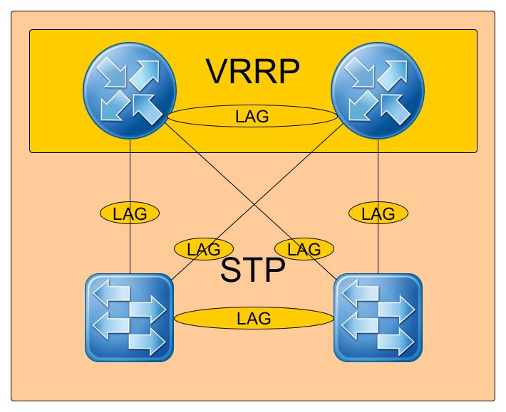
In a traditional design, then with a couple of switches (at least four), you configure VRRP for L3 redundant default gateway service, LACP – link aggregation groups for L2 link redundancy and some version of STP for L2 path redundancy, ending up in tons of blocked links and so on. Nevertheless attached switches can get redundant uplinks in any case of broken device or link.
Compared to that the VSF – Virtual Switching Framework, colloquially referred to as front side stacking implements both levels of redundancy in one layer. Link aggregation can be spread over chassis, implementing Layer 2 path and link redundancy even without spanning tree and the routing is done by the switches within the VSF. The only caveat is again, that MAD – multiple active detection – needs to be activated with an outside switch (painted south) to prevent split brain effects within the switch cluster.
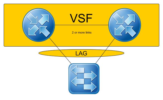
Analogous to IRF per VSF member two virtual ports (containing possibly mutliple links) can be defined implementing a ring, with only port 1 on member 1 linked to port 1 on member 2, when limiting to a two node cluster.
Which brings a configuration like the following and on the already configured master switch activate VSF like, as follows:
vsf member 1 link 1 9

vsf enable domain 10
This includes port number 9 on switch 1 of the vsf to the vsf link 1. Then a VSF domain identifier is set and this vsf enabled, resulting in the switch to reboot. Given a factory default second switch there seems to be no need of configuration on the second device and it will be added to the VSF.
Nevertheless, if you have already configured the second switch (to update the firmware for instance) you then can add it similarily to the same VSF domain, e.g.:
vsf member 2 link 1 9

vsf enable domain 10
Here adding as well port 9 to the link 1 on member switch two.
Make sure the second device boots second and the link between the two devices is not established before the second device is properly booting. I prefer to disconnect bot devices now, when changing the configuration on the second devices, since I got some hanging boots, if not having this properly separated.
After the reboot the switching fabric only answers on the ip of the master node – member one – from the creation cycle. With that, the different chassis are refered to by their number and the “slot” shows up in the port numbering scheme and needs to be adressed properly in the future. The existing port configurations are migrated to the new syntax. Given trunk configurations, particular when conflicting, may vanish and with them their vlan assignments.
Now you may add more redundant links to the VSF by e.g. – keep in mind you have only one management interface left:
vsf member 1 link 1 10

vsf member 2 link 1 10
In this case we add port 10 on member one to the existing link 1 and the same with port 10 on member two. Now simply plug in the cable and the redundant connection should show up. You may verify the link configuration and the VSF forming as follows.
RSLABSAMPLE# show vsf link detail
VSF Member: 1 Link: 1
Port     State

-------- ------------

1/9 Up:  Connected to port 2/9

1/10 Up: Connected to port 2/10
VSF Member: 2 Link: 1
Port     State

-------- ------------

2/9 Up:  Connected to port 1/9

2/10 Up: Connected to port 1/10
Now their is still one thing to do, prohibiting split brain by activating MAD. Basically the switches support two types of MAD, vlan-mad and lldp-mad. Since the vlan is limitted to one port and I encourage the use of linklayer discovery protocol (lldp) anyway I prefer the lldp MAD configuration which then needs SNMP configured on a probably by a spread link aggregation group connected quorum device (switch).
vsf lldp-mad ipv4 192.168.178.2 v2c "your-snmp-community"
So simply define the lldp-mad with the ipv4 address of your quorum device, providing an SNMP protocol version, here 2c and an valid SNMP community. Immediately you may validate the result of this MAD detection with show vsf lldp-mad status. This results e.g. in:
RSLABSAMPLE# show vsf lldp-mad status
MAD device IP                      : 192.168.178.2

MAD-probe portset                  : 1/8,2/8
VSF split                          : No

MAD probe originator               : No

Number of probe requests sent      : 0

Number of probe responses received : 0

MAD Active Fragment                : Yes
Indicating that on the ports 8 on both VSF members the quorum is reached and the MAD is active, as well as the VSF is right now healthy and “not split”. Requesting a show vsf lldp-mad parameters may reaport a readiness “Success”.
All by all now your running configuration regarding VSF should read like this:
vsf

enable domain 10

member 1

type "JL258A" mac-address 20677c-c672f0

priority 128

link 1 1/9-1/10

link 1 name "I-Link1_1"

exit

member 2

type "JL258A" mac-address 20677c-c6b085

priority 128

link 1 2/9-2/10

link 1 name "I-Link2_1"

exit

lldp-mad ipv4 192.168.178.2 v2c "your-snmp-community"

port-speed 10g

exit
With that checked, enjoy your fully redundant two switch network environment, providing available services to your local net.
Kyp.F.
Pingback: How To: Firmware Upgrade on an VSF-Stack | MyBenke.org